Full Energy vs Low Energy Automatic Door Openers: What's the Difference? | Automatic Door and Hardware![]()
Full Energy vs Low Energy Automatic Door Openers: What's the Difference?
When it comes to automatic door openers, there are two main types: full energy and low energy. The key difference between these two types of openers is the amount of force they use to open and close the door. Here's a closer look at each type:
Full Energy Automatic Door Openers
Full energy automatic door openers use a higher amount of force to open and close the door. These types of openers are typically used in high-traffic areas, such as hospitals or airports, where the door needs to open and close quickly and frequently. Full energy automatic door openers are subject to ANSI A156.10 safety requirements, which can include:
- Guide Rails
- Sensors
- Closing Speed Time
- Safety Signage
- Knowing Act Actuation
Guide Rails
6.1 Guide Rails for Swing Doors (See Figures A-2, A-4 & A-H)
6.1.1 Two guide rails shall be installed on the swing side of each door. Rails shall project at least to the leading edge ofthe widest door in the fully open position.
Exception #1: A wall or separator is permitted to be used in place ofa rail, provided that it meets the criteria in 6.1.2 through 6.1.5.8
Exception #2: Guide rails for swinging doors serving both egress and ingress shall project out from the face of the door jambs on the swing side to no less than the outside leading edge of the open door plus 55 inches (1400 mm) (See Figure A-2 & A-4).
6.1.2 A guide rail shall be 30 inches (760 mm) high minimum measured from the floor surface.
6.1.3 A guide rail shall have a panel or a divider to inhibit access to the protected area.
6.1.4 There shall be 6 inches (150 rum) maximum clearance between the rail and the door in the fullyopen position or between the rail and the leading edge of the door at the point in its arc of travel when it is closest to the rail. There shall be a 2 inch (51 mm) minimum clearance between the rail at the hinge side and the door in the fully open position.
6.1.5 Free standing guide rails shall have a maximum dimension between the rail and jamb (or other adjacent surface) of 2 inches (51 mm).
Sensors Swinging Doors
8.1.1 Non-swing side activating detection areas shall have a minimum width equal to the width of the door opening less 5 inches (125 mm) maximum from both sides for a total of 10 inches (255 mm) maximum measured at 15 inches (380 mm) and 30 inches (760 mm) perpendicular from the face of the closed door. The length from the face of the door shall be 43 inches (I090 mm) minimum measured at the center of the door opening. Detection shall be effective to within 5 inches (125 mm) from the face of the door measured at the center of the door opening (See Figure A-12A).8.1.2 A safety zone shall be provided on the swing side of all power operated swinging doors.12
8.1.2.1 If an overhead sensor(s) is used to provide a safety zone, the length of the active area shall be effective to within 5 inches (125 mm) of the face of the closed door measured at the center of the door opening. The safety zone shall extend 5 inches (125 mm) minimum beyond the leading edge of the door in the open position when measured at the center of the door opening. The width of the active area measured perpendicular from the face of the closed door shall be the door opening less 5 inches (125 mm) maximum measuring both sides for a total of 10 inches (255 mm) maximum measured parallel to the face of the door at a distance of 15 inches (380 mm) and 30 inches (760 mm) (See Figure A-12A).
8.1.2.2 If a door mounted sensor is used to provide a safety zone, it shall provide an active area 5 inches (125 mm) maximum from the face of the door for the width of the door less 5 inches (125 rum) from the pivot point. A door mounted sensor on either side of the door shall detect a 28 inch minimum (710 mm) high person or equivalent in the swing path, during the opening or closing cycle and shall cause the door to reverse direction, stop or slow down to a maximum latch edge speed of 4 inches per second (100 mm per second) measured within 1 inch (25 mm) ofthe latch edge before any contact is made (See Figure 12B).
8.1.3 Swinging doors serving both egress and ingress shall have a safety zone on the swing side, as defined in 8.1.2 and an activating zone extending an additional 55 inches (1400 mm) from the leading edge o f the door in the open position (See Figure A-12A).
8.1.4 If a sensor is used for activation and a safety control mat is used as a safety zone, the exposed area of the safety control mat shall extend 5 inches (125 nun) minimum beyond the edge of the door in the open position and:
1) extend 5 inches (125 mm) into the non-swing side area of the door measured from the face of the door; or
2) the door opening area shall be provided with a presence sensor that shall be used to prevent a fully open door(s) from closing when a person is in the space between two non overlapping activation or safety detection areas; or
3) the door closing cycle shall have a delay of 4 seconds minimum after the activating area is clear; or
4) be equipped with a door mounted sensor on the non swing side as described in 8.1.2.2.
8.1.4.1 The width ofa safety control mat shall be in accordance with 7.3.1 (See Figure A-12A).
8.1.5 If the distance between the two non overlapping zones exceeds 8 inches (205 mm) when sensors areused to provide both an activation and a safety zones, the door system shall:
1) be equipped with a safety control mat; or
2) be equipped with a presence sensor across the door opening; or
3) have a door closing cycle delay of4 seconds minimum after the activation area is clear; or
4) be equipped with a door mounted sensor on the non swing side as described in 8.1.2.2.
KNOWING ACT DOOR ACTUATIONUse of an activating device which requires a knowing act to activate the automatic door shall meet the
9.1following requirements:
9.1.1 Be installed in a location within view ofthe automatic door; and
9.1.2 Have an installation height of a minimum of 36 inches (915 mm) and a maximum of 48 inches(1220 mm); and
9.1.3 Be located a maximum distance of 12 feet (3.7 m) from the center of the door; and
9.1.4 The door shall remain open for a minimum of 5 seconds after release of the activating device; and
9.1.5 The door shall be equipped with a safety zone(s) as required in this standard for the type door anddetection system selected.
9.1.5.1 The door shall be equipped with a secondary activating zone of size and function as defined in 7.4.3 or 8.2.3.
10. ENTRAPMENT PROTECTION
10.1 Entrapment Protection measurements shall be taken under neutral air pressure conditions.
10.2 The force required to prevent a stopped power operated swinging door from moving in the directionof closing shall not exceed a 40 lbf (180 N) applied 1 inch (25 mm) from the lock edge of the door at any point in the closing cycle.
10.3 The opening time of a swinging or folding door to back check shall not be less than 1.5 seconds.
10.4 The force required to prevent a stopped power operated swinging door in the last 10 degrees ofopening from moving in the direction of opening shall not exceed 40 lbf (180 N) applied 1 inch (25 mm) from the lock edge of the door.
10.4.1 For folding doors, the force required to prevent a stopped door, in the last 10 degrees of the opening, from moving in the direction of opening shall not exceed 40 lbf (180 N) applied 1 inch (25 mm) from the leading edge ofthe FS leaf.16
10.5 A door shall not close through the final 10 degrees for swinging doors or no less than 2 inches (51 mm) for folding doors in less than 1.5 seconds.
10.6 Swing, sliding and folding doors utilizing sensors or control mats shall remain open a minimum of 1.5 seconds after loss of detection.
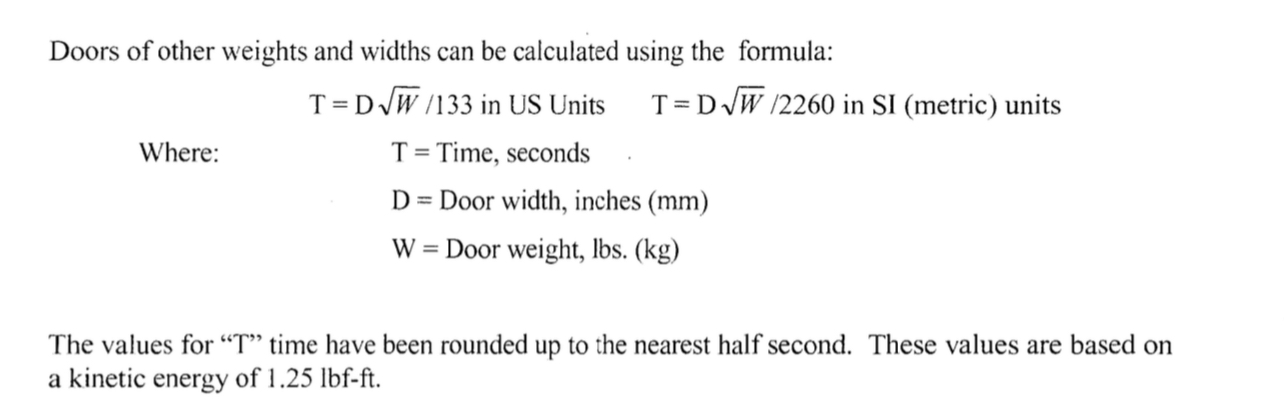
10.7 A swinging door shall be adjusted so that closing time to latch check shall be the minimum values of the following:
![]()
10.8 Clearance. Center pivoted swinging & folding doors shall have provisions for finger guard protection if the door clearance at the hinge side is greater than 114 inch (6.4 mm) and less than 3/4 inch (19 mm) with the door in any position.
11. SIGNAGE
11.1 All swinging, sliding and folding doors shall be equipped with signage visible from both sides reading, "AUTOMATIC DOOR" with letters 112 inch (12.7 nun) high minimum. The sign described in 11.2.3 shall be permitted to be used to satisfy this requirement.
11.2.l An arrow sign (See Figure 1.) shall be visible from the approach side of a swinging door mounted on the door at a height 58 inches::t 5 inches (1475 ±125 mm) from the floor to the center line of the sign. The sign shall be a minimum of 6 inches (150 mm) in diameter, having a green circle surrounding a black arrow on a white background.
11.2.2 An international "DO NOT ENTER" sign (See Figure 2.) shall be visible from the side of doors that swings or folds towards pedestrians attempting to travel in the wrong direction mounted on the door at a height 58 inches ±5 inches (1475 ±125 mm) from the floor to the center line of the sign. The sign shall be a minimum of 6 inches (150 mm) in diameter, having a red circle with the wording, "DO NOT ENTER", in the red circle.
11.2.3 Swinging doors serving both egress and ingress shall be marked with a decal, visible from the swing side of the door, with the words "AUTOMATIC CAUTION DOOR" (See Figure 3). The sign shall be mounted on the door at a height 58 inches ±5 inches (1475 ±125 nun) from the floor to the center line of the sign. The sign shall be a minimum of 6 inches (150 mm) in diameter and with black lettering on a yellow background.
![]()
11.5 Knowing Act Doors The door shall have signage which says "Automatic Door - Activate Switch to Operate" in 112 inch (13 mm) letters along with other required signage visible from each side ofthe door.
12. GENERAL PERFORMANCE
12.1 Latch Check. Latch check shall occur for swinging doors at no less than ten degrees from closed position and for sliding and folding doors at no less than 2 inches (51 mm) from the closed position.
12.2 Manual Opening Force for Swinging Doors. In the event of a power failure, the door shall be capable of opening with no greater than a 30 lbf (133 N), applied one inch (25 nun) from the edge of the lock stile.
12.3 Break Away Device for Swinging and Folding Doors. Swinging and folding doors provided with a break away device shall require no more than 50 lbf (222 N) applied 1 inch (25 mm) from the edge of the lock stile to open. When the door is opened in the break out mode, powered operating components excluding spring power shall not operate the door.
12.4 Break Away Device for Sliding Doors. Sliding doors provided with a break away device shall require no more than a 50 lbf (222 N) applied 1 inch (25 mm) from the leading edge of the lock stile for the break out panel to open. Break away devices (swinging panels) for doors that slide on the egress side of an opening shall be equipped with a self closing device or interrupt actuation of the operator when used in the break out mode. Break away devices incorporating swing out side lites shall interrupt actuation of the operator when used in the break out mode (See Appendix D1.3).
12.5 Break Away Egress Test for Swinging, Folding and Sliding Doors.
12.5.1 Doors with power operators shall be installed in a simulated wall and door framing assembly of sufficient strength to withstand all forces required by the tests. Installation shall be in accordance with manufacturer's printed instructions. Maintenance and repair of other than break away equipment is permitted to be performed during the testing cycles.
12.5.2 The test specimen shall be of the largest door size to be listed by the manufacturer.
12.5.3 Cycle for 300,000 cycles at a rate of 5 to 8 per minute.
12.5.4 Break away devices shall not be lubricated or adjusted during the test.
12.5.5 At every 50,000 cycles during the test, the doors shall undergo 1,000 break out cycles. At the conclusion ofthe test, break out forces shall not exceed those listed in 12.3 and 12.4.
12.6 Salt Spray Test
12.6.1 A sample of the latching and hinge assembly of the break away device of a power operated door contained in an approximately 25 inch (635 mm) wide panel shaH be subjected to a salt fog test in accordance with ANSIIBHMA AI56.18-1993 for Materials and Finishes for 168 hours.
12.6.2 Record the release force prior to conducting the test. This shall not exceed 50 lbf (222 N).
12.6.3 At the conchsion of the exposure time, remove the sample and allow to dry for 24 hours without cleaning.19
12.6.4 Then cycle the sample 10 times. The release force for the first cycle shall not exceed a 1001bf(445 N). Release forces for the next 9 cycles shall not exceed 50 lbf (222 N).
12.7 Testing Laboratory
12.7.1 Tests described in 7.7.3 and 12 shall be performed under the supervision of a nationally recognized independent testing laboratory on preproduction samples prior to acceptance of the design for production and subsequent installation. Production units shall be under an in-plant follow-up inspection service.
Low Energy Automatic Door Openers
Low energy automatic door openers use a lower amount of force to open and close the door. These types of openers are typically used in areas with lower traffic, such as offices or retail stores. Low energy automatic door openers are subject to ANSI safety requirements as well, but the requirements are less stringent than those for full energy automatic doors. Some of the ANSI A156.19 safety requirements for low energy automatic doors which can include:
- Opening / Closing Time
- Signage
4. REQUIREMENTS FOR LOW ENERGY SWINGING POWER OPERATED DOORS OR LOW ENERGY SWINGING POWER OPEN DOORS
4.1 Opening Time
4.1.1 Doors shall be field adjusted so that opening time to back check or 80 degrees, which ever occurs first, shall be 3 seconds or longer as required in Table I. Backcheck shall not occur before 60 degrees opening.
4.1.2 Total opening time to fully open shall be as in Table II. 4.2 Closing Time
4.2. I Doors shall be field adjusted to close from 90 degrees to 10 degrees in 3 seconds or longer as required in Table J.
4.2.2 Doors shall be field adjusted to close from 10 degrees to fully closed in not less than 1.5 seconds.
4.3 The door shall be field adjusted to remain fully open for not less than 5 seconds.
4.4 The force required to prevent a stopped door from opening or closing shall not exceed a 15Ibf (67 N) applied I in (25 mm) from the latch edge of the door at any point in the opening or closing cycle.
4.5 The kinetic energy of a door in motion shall not exceed 1.25 Ibf-ft (1.69 Nm). Table I provides speed settings for various widths and weights of doors for obtaining results complying with this paragraph.
4.6 In the event of power failure to the operator, doors shall open with a manual force not to exceed a 15 Ibf(67 N) to release a latch, if equipped with a latch, a 30 Ibf(133 N) to set the door in motion, and a 15 Ibf (67 N) to fully open the door. The forces shall be applied at 1" (25 mm) from the latch edge of the door.
5. CYCLE TESTS
5.1 Low Energy Power Operated, Low Energy Power Open, and Power Assist doors shall be cycle tested for 300,000 cycles.
5.2 Use the widest and heaviest test specimen recommended for use by the manufacturer. Narrower or lighter doors of the same configurations shall then be considered to meet the cycle test requirements.6
5.3 Use the requirements in Table 1 to detem1ine opening and closing speeds. Open the door to a 90 ± 5 degree open position and close the door to the 0 + 2 degree closed position using appropriate equipment. One opening and closing constitutes one cycle. In the case of Power Assist doors, use an actuator exerting an equivalent force equal to a 15 Ibf (67 N) measured at I in (25 mm) from the latch edge of the door applied in the opening direction and allow the closing device furnished to close the door.
5.4 At the conclusion of the cycle test, the doors shall operate in accordance with requirements of Table 1 and the actual opening and closing time shall be within ± 10 % of their respective values at the commencement of the test.
Minimum Opening Time to Backcheck or 80 degrees, which ever occurs first, and the Minimum Closing Time from 90 degrees to Latch Check or 10 degrees.
![]()
![]()
![]()
Note: To determme maximum times from close to full open, the operator shall be adjusted as shown in the chart. Backcheck occurring at a point between positions in Table II shall use the lowest setting. For example, if the backcheck occurs at 75 degrees, the full open shall be the time shown in Table I plus 1.5 seconds.
6. SIGNS
6.1 Doors shall be equipped with (a) sign(s) visible from either side, instructing the user as to the operation and function of the door. The signs shall be mounted 50" +/- 12" (1270mm +/- 305mm) from the floor to the center line of the sign. The letters shall be 5/8" (16 mm) high ml11llTIum.
6.3 Low Energy Doors All low energy doors shall be marked with a sign, visible from both sides of the door, with the words "AUTOMATIC CAUTION DOOR" (See Figure 1.). The sign shall be a minimum of 6 inches (152 mm) in diameter and with minimum 5/8"(l6mm) tall black lettering on a yellow background. Additional information may be included.
![]()
6.3.1 When a separate wall switch is used to initiate the operation of the door operator, the doors shall be provided with signs on both sides of the door with the message "ACTlVATE SWITCH TO OPERAIE". Ihe lettering shall be white and the background shall be blue.
6.3.2 When door motion is used to initiate the operation of the door operator, the doors shall be provided with the message "PUSH TO OPERATE" on the push side of the door and "PULL TO OPERATE" on the pull side of the door. The lettering shall be white and the background shall be blue.
At Automatic Door and Hardware, we offer a wide range of automatic doors and replacement parts to fit your commercial building needs, including both full energy and low energy automatic door openers. Contact us today to learn more about our selection!
Automatic doors and replacement parts are available for sale at the best prices at
www.autodoorandhardware.com.
Note this article is for reading purposes only and is not advice. All automatic doors should follow original manufacturer’s installation instructions and the most current ANSI requirements.